When a computer is turned on, special firmware that is stored in non-volalite memory is run. The three most popular kinds are BIOS, UEFI, and Coreboot.
The original BIOS (Basic Input/Output System) was created for an IBM PC in the 70s. Since there was no official spec, PCs since then have conformed to match its behavior. The BIOS's goal is to iterate through all of the attached media until it can successfully boot from one. At start-up, the CPU executes the BIOS program, and on x86 chips this will happen in 16-bit mode (also called real mode). During boot, the BIOS loads the first block from disk, called the Master Boot Record (MBR), which contains bootstrapping code, a partition table, and the disk signature. The MBR is 512 bytes and is loaded into the physical address 0x7C00. Why? Apparently, this was a conscious decision by the IBM PC 5150 development team to leave surrounding memory available for interrupt vectors, the BIOS, and the OS. The BIOS checks that the signature matches 0xAA55 and proceeds to execute the boostrapping code.
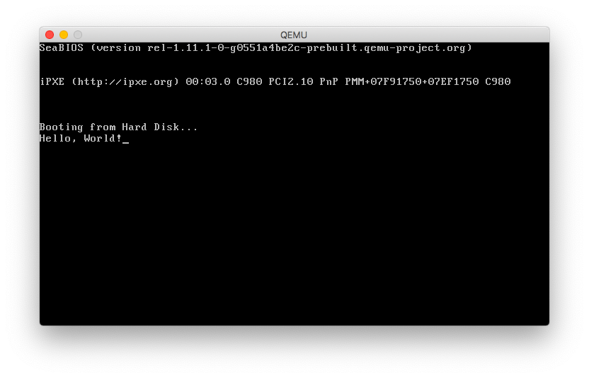
I put together a simple BIOS-based boot program that prints "Hello, World!" to the screen. The source can be found on the boot-bios-helloworld branch of my oscons GitHub repository. I use YASM to assemble the source into a ELF object file named boot.o,
$ yasm -f elf boot.asm -o boot.o
ld to link the object file into a binary that ensures the binary is loaded at address 0x7C00 and the last two bytes of the boot sector are 0xAA55,
$ ld.lld boot.o -N -T script.ld -b binary -o boot.img
the linker script used by ld to express these constraints holds the following,
SECTIONS {
    /* Define that the text section should be loaded at 0x7C00. */
    .text 0x7C00 : {}
    /* Place Boot Signature at the last two bytes of the sector. */
    . : AT(ADDR(.text) + 510) {
        SHORT(0xAA55);
    }
}
objcopy to strip the binary of its ELF headers and produce the resultant disk image,
$ objcopy boot.img -S -O binary
and QEMU to emulate either an i386 or x86_64 machine with this image loaded onto its disk.
$ qemu-system-<i386|x86_64> -drive format=raw,file=boot.img
We first issue a directive to tell YASM that we are assembling 16-bit instructions.
bits 16
The BIOS interrupt vector 0x10 contains handlers that perform video services. For this program, we want to write to the Teletype, so we specify 0x0E as the handler in the AH register. This handler takes in the character to write in the AL register, so we can make use of the LODSB instruction to iterate through the characters stored at HELLO_STRING, which expects the offset from the segment to be stored in the SI register.
mov          si, HELLO_STRING
mov          ah, 0x0E
Now we just loop over the NULL-terminated string and print each character by calling the interrupt. Once we've reached the end of the string, terminate the program.
.loop:
    lodsb
    cmp          al, 0
    je           end
    int          0x10
    jmp          .loop

end:
    hlt
Make sure to declare the string constant in memory.
HELLO_STRING: db "Hello, World!", 0
Executing this bootloader program should result in output like this:
Bootloaders will often run in multiple stages, in order to access more program memory. The bootstrapping code in the MBR will usually load another block corresponding to the Volume Boot Record (VBR), which is located in a separate partition that is found by scanning the MBR's partition table. Eventually the loader will want to enter protected mode, with access to a larger address space and 32-bit registers.
This process involves setting up the Global Descriptor Table (GDT), and enabling the A20 Line. Real mode uses segmented addressing, where two segment registers can store a logical address composed of a 16-bit base and 16-bit offset. Its 20-bit physical address is computed as (base<<4) + offset. Protected mode uses descriptors to translate logical addresses to physical addresses.
The GDT contains 8-byte entries, each of which has a base address, segment length, and other configurable attributes like access permissions. Indexes into the GDT are called selectors. Every GDT is required to have its first descriptor be NULL. By initializing unused segments with this entry, an exception is triggered when unused segments are referenced. The GDT can be loaded with the LGDT instruction.
Interrupts are a way to notify the CPU about an event, and have it execute some code. In real mode, a table of interrupt handlers is loaded and reserved between the physical addresses 0x0000 and 0x03FF, where each pointer is 4 bytes. These range from division-by-zero to BIOS interrupts that can write to the screen. Entering protected mode will require disabling interrupts beforehand. In protected mode, there is no predefined table, and BIOS interrupts are no longer accessible.
In order to address up to 4GB of memory, the 21st (indexed from zero) address line must be explicitly be enabled. Why isn't this enabled by default? Before processors with more than 20 address lines were introduced, accessing an address past 1MB would wrap around. Some engineers depended on this behavior, so in an effort to stay backwards compatible, the 21st address line (A20 line) is disabled by default. There are many ways of turning on the A20 line, all of which are required to have the widest processor support.
Finally, set the Protected Mode Enable (PE) bit in CR0, a control register. Perform a jump to a far address to clear the prefetch queue, and initialize protected mode. This will involve initializing the segment registers with a data segment from the GDT and jumping into the kernel.
This example extends the helloworld example above to enter protected mode, and prints a message indicating its success. The source can be found on the boot-bios-protected branch of my oscons GitHub repository. The build instructions have not changed, but there is additional work involved before printing a message. The first thing to note is that we want to print in protected mode by writing to video memory. The most convenient way to do this is to set the video mode to support 80x25 16 color text during boot, before entering protected mode. This can be done with the video services interrupt 0x10, and the AH=0, AL=3.
mov          ax, 0x3
int          0x10
We can now begin the process of entering protected mode by setting up the GDT. Under the gdt label, we define three 8-byte values representing each descriptor. Additionally define a pointer structure under the GDT_ADDR label which specifies the GDT's limit (size in bytes - 1) and starting physical address.
gdt:

;   NULL Descriptor
;  ┌──────┬───────┬───────┬────────┬──────┬───────┐
;  │ Base │ Flags │ Limit │ Access │ Base │ Limit │
;  ├──────┼───────┼───────┼────────┼──────┼───────┤
;  │ 0x0  │ 0x0   │ 0x0   │ 0x0    │ 0x0  │ 0x0   │
;  └──────┴───────┴───────┴────────┴──────┴───────┘
    dq 0

;   Code Segment Descriptor                           Flags
;  ┌──────┬───────┬───────┬────────┬──────┬────────┐ ┌─────────────┬──────┬──────┬───────┐
;  │ Base │ Flags │ Limit │ Access │ Base │ Limit  │ │ Granularity │ Size │ Long │ Extra │
;  ├──────┼───────┼───────┼────────┼──────┼────────┤ ├─────────────┼──────┼──────┼───────┤
;  │ 0x0  │ 0xB   │ 0xF   │ 0x9A   │ 0x0  │ 0xFFFF │ │ 0b1         │ 0b1  │ 0b0  │ 0b0   │
;  └──────┴───────┴───────┴────────┴──────┴────────┘ └─────────────┴──────┴──────┴───────┘
;   Access
;  ┌─────────┬───────────┬──────┬────────────┬───────────┬────────────┬──────────┐
;  │ Present │ Privilege │ Type │ Executable │ Direction │ Read/Write │ Accessed │
;  ├─────────┼───────────┼──────┼────────────┼───────────┼────────────┼──────────┤
;  │ 0b1     │ 0b00      │ 0b1  │ 0b1        │ 0b0       │ 0b1        │ 0b0      │
;  └─────────┴───────────┴──────┴────────────┴───────────┴────────────┴──────────┘
    dq 0x00CF9A000000FFFF

;   Data Segment Descriptor                           Flags
;  ┌──────┬───────┬───────┬────────┬──────┬────────┐ ┌─────────────┬──────┬──────┬───────┐
;  │ Base │ Flags │ Limit │ Access │ Base │ Limit  │ │ Granularity │ Size │ Long │ Extra │
;  ├──────┼───────┼───────┼────────┼──────┼────────┤ ├─────────────┼──────┼──────┼───────┤
;  │ 0x0  │ 0xB   │ 0xF   │ 0x92   │ 0x0  │ 0xFFFF │ │ 0b1         │ 0b1  │ 0b0  │ 0b0   │
;  └──────┴───────┴───────┴────────┴──────┴────────┘ └─────────────┴──────┴──────┴───────┘
;   Access
;  ┌─────────┬───────────┬──────┬────────────┬───────────┬────────────┬──────────┐
;  │ Present │ Privilege │ Type │ Executable │ Direction │ Read/Write │ Accessed │
;  ├─────────┼───────────┼──────┼────────────┼───────────┼────────────┼──────────┤
;  │ 0b1     │ 0b00      │ 0b1  │ 0b0        │ 0b0       │ 0b1        │ 0b0      │
;  └─────────┴───────────┴──────┴────────────┴───────────┴────────────┴──────────┘
    dq 0x00CF92000000FFFF

GDT_ADDR:
    dw           24-1
    dd           gdt
Our booting code can now load the descriptor table with
lgdt [GDT_ADDR]
The next step is to enable the A20 line. We should define a procedure to check that the A20 line has been enabled, so we can call it after each attempt. The key logic here is to write a 0x00 byte to 0x0000:0x0500 and 0xFF byte to 0xFFFF:0x0510. If the byte at 0x0000:0x0500 is 0xFF, then the access wraps around, and the A20 line is not enabled.
checkA20:
    push         ds
    push         es
    mov          ax, 0xFFFF
    mov          ds, ax
    not          ax
    mov          es, ax
    mov          cx, word [es:0x0500]
    mov          dx, word [ds:0x0510]
    mov          byte [es:0x0500], 0x00
    mov          byte [ds:0x0510], 0xFF
    cmp          byte [es:0x0500], 0xFF
    mov          word [es:0x0500], cx
    mov          word [ds:0x0510], dx
    je           checkA20__exit
    mov          ax, 1
checkA20__exit:
    pop          es
    pop          ds
    ret
One of the A20 enabling mechanisms will attempt to interact with the 8042 Keyboard Controller, but since that is a blocking operation, we must define a procedure to wait until the I/O port of the keyboard controller is not busy.
waitIO:
    in           al, 0x64
    test         al, 0x2
    jnz          waitIO
    ret
Now our A20 enabling procedure can be defined.
enableA20:
    ; ...body of procedure...
enabledA20:
    ret
In the body, we first do an initial check that A20 is enabled.
call         checkA20
cmp          ax, 0
jne          enabledA20
The first mechanism is to perform a BIOS interrupt 0x15 with AH=0x24, AL=01. Not all BIOS's support this ability, so we check after performing the interrupt.
mov          ax, 0x2401
int          0x15
call         checkA20
cmp          ax, 0
jne          enabledA20
If that fails, we try the most traditional approach of sending a write command (0xD1), followed by an A20-enabling command (0xDF) to the keyboard controller. 0x64 represents the controller's command register only for writing, while 0x60 is a data port for both reading and writing.
call         waitIO
mov          al, 0xD1
out          0x64, al
call         waitIO
mov          al, 0xDF
out          0x60, al
call         checkA20
cmp          ax, 0
jne          enabledA20
The last attempt to enable A20 is to set bit 1 on a byte from System Control Port A (0x92). We do this method last because it can crash. Note, we don't do conditional jump after it since the immediately succeeding instruction is a ret, and the value in the AX register is already set.
in           al, 0x92
or           al, 2
out          0x92, al
call         checkA20
Now that all of the A20-related procedures have been defined, we can try enabling it. If it fails, branch to where the failure string is printed.
call         enableA20
cmp          ax, 0
je           failedA20
Printing the failed string works exactly like printing the hello-world string in the previous example.
failedA20:
    mov          si, FAILED_STRING
    mov          ah, 0x0E
.loopFailedA20:
    lodsb
    cmp          al, 0
    je           endFailedA20
    int          0x10
    jmp          .loopFailedA20
endFailedA20:
    hlt
We just make sure to declare our NULL-terminated string constants.
FAILED_STRING: db "Failed to Enter Protected Mode.", 0
SUCCESS_STRING: db "Successfully Entered Protected Mode.", 0
Otherwise, we can now enter protected mode. We should first disable interrupts with the cli instruction, as to not only prevent exceptions while enabling protected mode, but also since future interrupt handling will require us to set up the Interrupt Descriptor Table (IDT).
cli
We just have to set the Protected Mode Enable (PE) bit on the special CPU register CR0.
mov          eax, cr0
or           eax,0x1
mov          cr0, eax
Finally, we long jump into protected mode, to clear the CPU's prefetch queue. Note that the address here references the code segment, defined in the GDT, whose selector is 1. The hardware wants the segment value to be the selector multiplied by 8.
jmp 0x8:protectedMode
Printing the success string is slightly different than the failure string, because we now write directly to the text output of the video memory, located at the physical address 0xB8000. For each character we print, increment the pointer by 2, since each entry for a character is accompanied by an attribute (like its color). In this case, 0xF represents white, so we OR it with AH, and write AX to video memory.
protectedMode:
    bits         32
    mov          esi, SUCCESS_STRING
    mov          ebx, 0xB8000
.loopSuccess
    lodsb
    cmp          al, 0
    je           end
    or           ah,0xF
    mov          [ebx], ax
    add          ebx, 2
    jmp          .loopSuccess
end:
    hlt
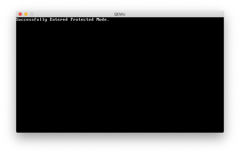
If the bootloader was able to successfully enter protected mode, you should see output like the following:
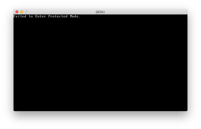
Otherwise, you should see:
NOTE: There is an additional process when entering long mode, a.k.a 64-bit mode, which involves CPU feature detection, setting up paging, setting the long mode bit in the model-specific-register, and updating the GDT and IDT.